Effect of heat treatment process on temperature field and stress field of laser cladding 316L
In order to study the regulating effect of different heat treatment processes on the residual stress of laser cladding, a thermal-mechanical coupling model was established using ANSYS finite element analysis software, and the temperature field and stress field of laser cladding 316L stainless steel under different temperatures (22~900 ℃) preheating treatment, different temperatures (200~1000 ℃) post-cladding annealing treatment, and coordinated heat treatment before and after cladding were numerically simulated. The research results show that preheating has the greatest impact on the molten pool temperature, and the molten pool temperature increases with the increase of preheating temperature; annealing treatment has the best effect on improving the residual stress of laser cladding, and 800 ℃ annealing treatment can reduce the residual stress by about 50%, followed by coordinated heat treatment before and after cladding, which can reduce the residual stress by about 35%. Preheating treatment has a certain improvement on the residual stress of laser cladding, among which preheating at 500 ℃ can reduce the residual stress by about 20%.
Laser cladding is a surface modification technology that uses high-energy laser beams to heat the cladding layer and the substrate at the same time, so that The cladding material and part of the substrate are melted together and cooled rapidly, so that a high-quality coating with good metallurgical bonding is obtained on the surface of the substrate. Laser cladding has the advantages of fast cooling, low coating dilution rate, small deformation, and easy automation. It can significantly improve the wear resistance, corrosion resistance and oxidation resistance of the substrate surface, and is therefore widely used [1-4]. Residual stress is one of the most important factors affecting the quality of laser cladding forming. The cracks, wear resistance and corrosion resistance of the cladding layer are closely related to the residual stress distribution. WANG et al. [5] avoided the generation of cracks in the hard surface coating by reducing the residual stress in the coating; Zhang Tiangang et al. [6] found that the probability of cracks in the stress concentration area of the coating is higher; ZHU et al. [7] and Guo Huafeng et al. [8] found that a certain residual compressive stress is beneficial to the improvement of the wear resistance of the coating; CRUZ et al. [9] found through research that compressive stress inhibited the SLM316L non-hardness. The film growth of stainless steel was inhibited, the repassivation kinetics was reduced, and the pitting corrosion resistance of 316L stainless steel was improved. Therefore, the distribution and regulation of residual stress, elimination or improvement of stress distribution, are of great practical significance for improving the performance of cladding layer.
The residual stress of laser cladding is closely related to the laser cladding process parameters[10], scanning strategy[11] and post-processing method[12]. At present, the research on the regulation of residual stress in laser cladding is mostly based on numerical simulation research on optimizing process parameters. VUNDRU et al.[13] established a thermal-mechanical coupling model of laser cladding of CPM9V powder on the surface of H13 tool steel using ABAQUS, and determined the optimal cladding process parameters for reducing tensile stress after analyzing the residual stress. Wang Lifang et al.[14] established a single-layer cladding model using ANSYS and explored the influence of process parameters on the residual stress of cladding layer. The results showed that scanning speed and laser power have the greatest influence on residual stress. et al. [15] established a sequential coupling model to simulate the temperature field and stress field in the laser additive manufacturing of Inconel 718 alloy under different process parameters and scanning strategies. The results showed that lower laser power, higher scanning speed and reasonable scanning strategy can effectively avoid stress concentration in cladding.
In addition, some scholars have also conducted numerical simulations on laser cladding under preheating conditions. Gu Zhaozhao [16] simulated the temperature field and stress field of coaxial powder feeding laser cladding. The study showed that preheating can significantly improve the residual stress distribution. Zhao Yuan [17] conducted a numerical simulation study on the laser cladding repair of curvature blades. The results showed that when the substrate preheating temperature increased from 220 ℃ to 420 ℃, both types of stress in the cladding layer of the variable curvature blade showed a downward trend. Cai Chunbo et al. [18] used SYSWELD to establish a three-dimensional finite element model. The process of laser cladding iron-based coating at different preheating temperatures was numerically simulated, the changing laws of temperature field and microstructure transformation at different preheating temperatures were analyzed, and the influence of cooling rate and microstructure transformation on residual stress field was studied.
Although some scholars have used numerical simulation methods to study the regulation of residual stress in laser cladding, most of them are to regulate residual stress by optimizing process parameters or preheating treatment. There is a lack of research on numerical simulation of regulating residual stress by heat treatment after cladding and coordinated heat treatment before and after cladding. Based on this, this paper established a three-dimensional thermoelastic-plastic model, and studied the influence of different heat treatment processes on the temperature field and stress field of laser cladding through thermal-mechanical coupling numerical simulation. By comparing the effects of preheating treatment before cladding, annealing treatment after cladding, and coordinated heat treatment before and after cladding on the residual stress of laser cladding, the optimal heat treatment process for regulating the residual stress of laser cladding was explored.
1 Finite element modeling and experimental methods
1.1 Establishment of finite element model of laser cladding
During laser cladding, under the irradiation of high-energy laser beam, the spot area and the substrate around it are rapidly heated to form a molten pool and produce elastic-plastic deformation. A large temperature gradient is generated between the molten pool and the surrounding substrate. Due to the differences in mechanical properties such as thermal expansion coefficient, elastic modulus, and yield strength of materials at different temperatures, the temperature gradient leads to uneven expansion and contraction, thus generating thermal stress.
When using ANSYS software to perform numerical simulation on the temperature field and stress field of laser cladding, since the temperature field has a great influence on the stress field, while the stress field has a small influence on the temperature field[19], a sequential thermal-mechanical coupling model is established. First, a Gaussian heat source is applied to the model using the APDL command stream, the temperature field is calculated, and the node temperature data is obtained. Then, the unit conversion function in the ANSYS software is used to convert the thermal unit in the model into a structural unit, and the corresponding structural boundary conditions are set. The temperature field node data is loaded into the model, thereby obtaining a finite element model of the laser cladding stress field. Further calculation of the stress field is performed to obtain the residual temperature of the laser cladding. The distribution of residual stress field.
1.1.1 Geometric modeling and meshing
The finite element model of single-pass single-layer laser cladding is shown in Figure 1. The size of the substrate is 40mm×30mm×8mm, and the size of the cladding layer is 30mm×2mm×0.5mm. The temperature in the cladding area changes dramatically, and the temperature gradient and stress are large. To ensure the calculation results, the model uses a hexahedral gradient grid, that is, the closer to the cladding layer, the denser the grid. As shown in Figure 1, the total number of units and nodes in the model is 14520 and 66373, respectively. The model freedom constraint adopts the three-point fixing method, and the X, Y, and Z direction constraints are applied to point A, the X and Y direction constraints are applied to point B, and the Z direction constraint is applied to point C.
In order to further analyze the spatial distribution law of the temperature field and stress field of the model, different analysis nodes and analysis paths are set on the model. As shown in Figure 1, a node is set at the connection between the cladding layer and the substrate along the laser scanning direction. X1(0.01,0,0), X2(0.02,0,0), X3(0.03,0,0); Y1(0.02,0,0), Y2(0.02,-0.001,0), Y3(0.02, -0.005,0) are set on the upper surface of the substrate in the transverse direction; Z1(0.02,0,0.0005), Z2(0.02,0,0.00025), Z3(0.02,0,0), Z4(0.02,0,-0.00025), Z5(0.02,0,-0.0005) are set in the middle of the cladding along the thickness direction. In order to study the residual stress distribution at different positions, four paths are set, as shown in Figure 1. Since the cladding layer will form a large longitudinal residual stress along the laser scanning direction, Path 1 and Path 2 are both set along the laser scanning direction. Path 1 is set at the junction of the cladding layer and the substrate. This is because the cladding layer and the substrate are made of different materials, and their elastic modulus, thermal expansion coefficient and other material properties are different, which is prone to stress concentration. Path 2 is set on the upper surface of the cladding layer to study the stress distribution on the surface of the cladding layer. Since the temperature gradient perpendicular to the laser scanning direction is the largest, the thermal stress generated is also correspondingly large. Therefore, Path 3 set along the transverse direction and Path 4 set along the thickness direction are both perpendicular to the laser scanning direction. Since stress concentration is prone to occur at the junction of the cladding layer and the substrate, which increases the possibility of crack generation, the selected path is mainly set here, which can well reflect the stress distribution characteristics of the entire model.
According to the literature, combined with Jmatpro material simulation software, the material thermal properties of the substrate 45 steel and the cladding material 316L that change with temperature are obtained, as shown in Figure 2.
1.1.2 Moving heat source loading
Since the laser heat source has a certain penetration depth, the laser cladding model The Gaussian distribution body heat source model is used in the simulation. This model can well describe the spatial distribution characteristics of the laser thermal power density attenuation along the height direction. The expression is: see formula (1) (2) in the figure
Wherein, Q is the heat flux density; η is the laser absorptivity, which is generally taken as 0.25 ~ 0.6, and 0.45 is taken in this paper; P is the laser power; R is the spot radius; r is the distance from any point in the space to the center of the spot; x0, y0, z0 are the starting coordinates of the laser scanning; v is the moving speed of the laser; t is the time.
In the calculation of the temperature field of the laser cladding process, the thermal convection module and thermal radiation module of the finite element model are used to apply thermal convection and thermal radiation on the model surface. The convection heat transfer coefficient is 10W/(m2.K), which is close to natural convection, and the emissivity is 0.4.
1.1.3 Heat treatment process parameters
The basic process parameters of laser cladding numerical simulation are: laser power 1200 W, scanning speed 5 mm/s, heat source radius 1.5 mm. The process parameters of heat treatment are composed of three factors: heat treatment method, preheating temperature, and annealing temperature, as shown in Table 1. This paper conducted a total of 9 groups of preheating treatment, 5 groups of annealing treatment, and 2 groups of laser cladding numerical simulation under the conditions of collaborative treatment.
1.2 Laser cladding experimental method
In order to verify the effectiveness of the finite element model, the cladding experiment was carried out using the same process parameters as the numerical simulation (laser power 1200 W, scanning speed 5 mm/s, heat source radius 1.5 mm), and the simulated temperature field cross section and the experimental molten pool morphology size were compared. The experiment used coaxial powder feeding laser cladding equipment, and the experimental principle is shown in Figure 3. The substrate is a 45 steel plate with a size of 40 mm, and its chemical composition is shown in Table 2. 30 molten m cladding m layer × 8 316L stainless steel powder was used, with a particle size of 45-106 μm and chemical composition as shown in Table 2. Before cladding, the substrate surface was sanded and then degreased with alcohol and acetone, and then dried together with the powder. After cladding, the sample was cut into 5 mm × 5 mm × 8 mm blocks using an electric spark wire cutting machine, and the cross section of the cladding layer was ground and polished. The polished block was washed with anhydrous ethanol and blown dry, and then placed in the prepared ferric chloride metallographic etching solution (95 mL concentrated hydrochloric acid + 3 mL hydrogen peroxide + 7.5 g ferric chloride). The etching solution completely soaked the block, and the surface was corroded for 5-10 seconds. After that, the surface of the corroded block was rinsed with anhydrous ethanol, and then the cross-sectional morphology of the coating was observed with a metallographic microscope.
2 Results and discussion
2.1 Temperature field distribution
2.1.1 Model verification
Figure 4 shows the temperature distribution of the sample obtained by numerical simulation without heat treatment. Temperature field of single-pass laser cladding at 3s. An ellipsoidal molten pool is formed at the laser irradiation position. The isotherms are denser along the laser scanning direction and gradually sparser in the solidification direction. As the heat source moves continuously in the X-axis direction, the molten pool moves forward continuously. The melting points of 45 steel and 316L are 1450℃ and 1370℃ respectively. The temperature of the molten pool is higher than the melting points of the substrate and the cladding layer, so the two can achieve metallurgical bonding.
Figure 5 shows the cross section of the simulated temperature field and the cross section of the molten pool obtained in the experiment. The cross section of the cladding layer can be divided into the cladding zone (CZ), the substrate melting zone (MZ), the heat affected zone (HAZ) and the substrate (SZ) [30-31]. Figure 5a shows the metallographic structure of the cross section of the specimen. The height of the cladding zone is H = 0.46 mm and the height of the substrate melting zone is h = 0.5 mm under the metallographic microscope. =0.64 mm, molten pool height H1 =1.1 mm, molten pool width W1 =2.3 mm, and heat affected zone width WHAZ1 =2.93 mm. Figure 5b shows the temperature field of the model cross section. The part with a temperature higher than 1450 °C forms a molten pool, and the part with a temperature of 900~1450 °C is the heat affected zone. By extracting the molten pool size contour line on the cross section, it can be obtained that the model molten pool height H2 =1.2 mm, molten pool width W2 =2.2 mm, and heat affected zone width WHAZ2 =2.9 mm. The size of the molten pool obtained by simulation and experiment is consistent well, which verifies the accuracy of the model [15,30]. In the actual cladding process, the molten pool has fluidity, so the cross section of the experimental molten pool is parabolic, but the fluidity of the molten pool is not considered in the simulation [32-33]. Therefore, the cross-sectional morphology of the simulated molten pool is slightly different from the parabolic shape of the experimental molten pool. In addition, MENG et al. [15] compared the cross section of the single-pass cladding experimental molten pool with the simulation results of the molten pool cross section in the simulation of the temperature field and stress field in the laser additive manufacturing of Inconel 718 alloy, and tested the residual stress on the surface of the cladding layer. The results showed that the average error between the simulation results and the experimental results of the residual stress was 7.26%, and the maximum error was 21%. CHEN et al. [33] compared the residual stress obtained in the simulation and experiment after verifying the experimental results of the molten pool cross section when studying the influence of overlap rate and scanning strategy on the residual stress of selective laser melting. The simulation results have the same trend as the experimental data, and the average error of the residual stress is less than 10%, and the maximum error is less than 20%. The research results show that the simulation results of the residual stress are in good agreement with the experimental results, indicating that the residual stress simulation of the model after verification of the molten pool cross section is reliable, reflecting the accuracy of this method.

2.1.2 Temperature distribution during cladding process
Figure 6a shows the temperature-time curves of three nodes (X1, X2, and X3) at the junction of the cladding layer and the substrate along the laser scanning direction. During cladding, the molten pool moves continuously along the scanning direction. When the heat source passes, the temperature rises rapidly to a peak value, and the temperature drops rapidly after the heat source passes, showing a transient nonlinear change curve. The temperature peaks of the X1, X2, and X3 nodes are 2633 ℃, 2695 ℃, and 2703 ℃, respectively. Due to the accumulation of heat during the cladding process, the temperature of the subsequent nodes is higher than that of the previous nodes. At the same time, due to the fast cladding speed, short time, and small heat accumulation, the temperature peaks of different nodes are not much different. Figure 6b shows the temperature-time curves of three nodes (Y1, Y2, and Y3) along the horizontal direction on the upper surface of the substrate. At 3s, the center of the heat source reaches the Y1 node, and the temperature of the Y1 node reaches 2695 ℃ at the highest. The temperature peaks of the Y2 and Y3 nodes gradually decrease, and the Y3 The temperature peak of the node is below 150 ℃, indicating that the thermal effect of the laser here is not obvious, which is consistent with the characteristic of small heat-affected zone of laser cladding. Figure 6c shows the temperature-time curves of 5 nodes (Z1, Z2, Z3, Z4, Z5) in the middle of the cladding along the thickness direction. The temperature of the Z1 node on the upper surface of the cladding layer is the highest, reaching 3206 ℃. The temperature peaks of the Z2, Z3, Z4, and Z5 nodes gradually decrease but are all above 1750 ℃, which can achieve metallurgical bonding.
Here, the change of the temperature of each node with time during the cladding process without heat treatment is analyzed. The temperature change trend and distribution characteristics of each node during the cladding process under the preheating and annealing heat treatment process are similar to this, so they will not be repeated.
2.1.3 Effect of heat treatment process on temperature
Figure 7 shows the temperature history of the Z4 node inside the molten pool in the middle of the scanning track during preheating treatment at 500 ℃ and annealing at 800 ℃. Without preheating treatment, the temperature of the Z4 node rises sharply from room temperature (22 ℃) after laser scanning, reaches a peak of 2290 ℃ at 3s, and the cladding is completed at 6s. Then the temperature gradually decreases and naturally cools down to 24.9 ℃ at 3600s. When 500 ℃ preheating treatment is performed before cladding, the temperature of the Z4 node rises sharply from 500 ℃ after laser scanning, reaches a peak of 2788 ℃ at 3s, and the cladding is completed at 6s. It naturally cools down to 43 ℃ at 3600s. When 800 ℃ annealing treatment is performed after cladding, the temperature of the Z4 node remains unchanged at 800 ℃ from 3600 to 21600s, and starts to cool naturally after 21600s. The temperature drops to 51.5 ℃ at 25200s (cooling for 1h). In general, before the cladding is completed, the temperature drop rate is very fast due to the continuous laser heat input. The temperature of the Z4 node is relatively slow, and the cladding is completed in 6s. Since there is no more heat input, the temperature drops sharply. As the temperature difference with the environment decreases, the cooling rate becomes slow again. In addition, the preheating treatment makes the temperature peak of the Z4 point higher than the cladding temperature peak without preheating, and the cooling rate slows down. Annealing treatment is a post-cladding treatment, so it has no effect on the temperature during the cladding process. Here, only the influence of the two heat treatment process parameters of 500 ℃ preheating treatment and 800 ℃ annealing treatment on the temperature history of the Z4 node is analyzed. Although the temperature of this node is slightly different under the heat treatment process parameters of other temperatures, the temperature history trend is consistent and will not be repeated.
2.2 Stress field analysis
The residual stress after cooling to room temperature after the laser cladding is completed has an important influence on the quality of the cladding layer. Therefore, this section focuses on the analysis of the residual stress of laser cladding, and the equivalent stress (vonMises stress) of the simulation model is used for evaluation.
2.2.1 Single-pass cladding stress field distribution
Figure 8 shows the residual stress distribution at the time of natural cooling to room temperature after the laser heating is completed. For equivalent stress, it can be seen from Figure 8a that, except for the small residual stress on the upper surface of the initial and final cladding layers, the entire cladding layer has a large residual stress. For the X-direction (longitudinal) stress, it can be seen from Figure 8b that the cladding layer and the area below it have a large tensile stress (about 600 MPa), and the area below is a compressive stress area with small stress. During the cooling process after the laser heating is completed, the shrinkage of the cladding layer is constrained by the surrounding substrate, resulting in a large tensile stress in the X direction, and compressive stress will be generated below due to the balance principle. For the Y-direction (transverse) stress, as shown in Figure 8c, there is a tensile stress (about 360 MPa) at the junction of the cladding layer and the substrate and its vicinity, and a compressive stress below. For the Z-direction (thickness direction) stress, as shown in Figure 8d, since the cladding layer has a small forming height in the thickness direction, the shrinkage resistance is small, which makes the residual stress of the cladding layer in the thickness direction The residual stress is very small (less than 100 MPa), and there is a small compressive stress in the entity below the cladding layer. By comparing the residual stress in each direction, it can be found that the stress in the X direction is significantly greater than the stress in the Y and Z directions, that is, the residual stress along the scanning direction is the largest. This is because the plastic tensile deformation of the cladding layer along the X direction (laser scanning direction) is much greater than that in the other two directions. Therefore, the equivalent stress distribution of a single cladding is most affected by the stress in the X direction. The residual stress in some areas of the figure exceeds the yield strength of the material. On the one hand, the extremely high temperature gradient during the laser cladding process leads to large residual stress; on the other hand, the material undergoes ideal elastic-plastic behavior in the simulation, which causes the material to undergo work hardening, causing the yield strength of the material to increase with the increase of plastic deformation.
Figure 9 is the residual stress distribution curve of each path obtained by collecting the vonMises stress (σvon) of each path. Figure 9a shows the equivalent stress at the connection between the cladding layer and the substrate along the laser scanning direction in path 1. Since the cladding layer will be strongly constrained by the surrounding entity when it cools and shrinks, the entire scanning path (5 The residual stress of the cladding layer (13.5 mm < X < 35 mm) reaches about 520 MPa and is evenly distributed. In addition, the residual stress of path 1 suddenly increases to 550 MPa at the starting point and the end point of cladding. This is due to the stress difference caused by the large difference in temperature field at the starting point and the end point of cladding. Figure 9b shows the residual stress of the cladding layer on the upper surface of path 2 along the laser scanning direction. The residual stress on the upper surface of the cladding layer is generally smaller than the residual stress at the connection. This is because there is no substrate constraint on the upper surface and deformation releases part of the stress. Figure 9c shows the residual stress of the substrate on the upper surface of path 3 along the transverse direction. There is a large residual tensile stress in the cladding layer and the adjacent area (13.5 mm < Y < 16.5 mm) and the stress is the largest at the connection between the cladding layer and the substrate (Y = 13.5 mm, Y = 16.5 mm). As shown in Figure 9d, the residual stress of path 4, that is, the middle part of the cladding in the thickness direction, shows a trend of decreasing first and then increasing. On the one hand, the bottom of the substrate is constrained by the stress. On the other hand, as the distance to the cladding layer increases, the heat input increases, and the stress shows an increasing trend.
Through analysis, it is found that the residual stress distribution of path 1 and path 2 along the scanning direction is relatively uniform, but there is a stress mutation at the beginning and end positions. In the transverse direction, the residual stress of path 3 suddenly increases at the boundary of the cladding layer, and the residual stress of path 4 in the thickness direction is mainly concentrated in the cladding area (8 mm away from the bottom of the substrate). The maximum residual stress of the four paths all appear at the connection between the cladding layer and the substrate. One is that the volume shrinkage during the cooling process of the molten pool is constrained by the substrate, resulting in stress concentration. The other is that the stress concentration is caused by the difference in the elastic modulus, thermal expansion coefficient and other thermophysical properties of the cladding layer and the substrate. Therefore, the connection between the cladding layer and the substrate is prone to cracking and other defects.
2.2.2 Stress distribution at different preheating temperatures
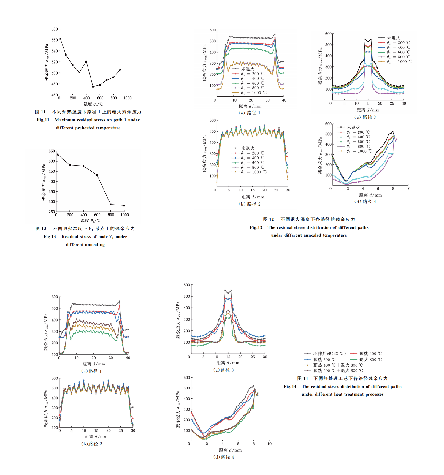
Laser cladding has the characteristics of fast heating and cooling. The temperature gradient is very large, and preheating the substrate can keep the temperature and cool slowly, which is an effective means to reduce residual stress and cracks. The residual stress distribution under different preheating conditions was obtained by numerical simulation. Figure 10 shows the residual stress curves of each path at different preheating temperatures θ0. As shown in Figure 10a, at different preheating temperatures, the residual stress of path 1, that is, the connection between the cladding layer and the substrate along the laser scanning direction, is reduced to varying degrees compared with the non-preheating cladding. When there is no preheating or the preheating temperature is 100~400℃, the residual stress of path 1 at the end of cladding (X = 35mm) is the largest; when the preheating temperature is 500~900℃, the improvement effect of the residual stress at the beginning and end of cladding on path 1 is significantly better than that in the middle of cladding. The residual stress at the end of cladding is no longer the maximum stress of the entire cladding path, and the residual stress at the beginning and end of cladding is significantly less than the residual stress at the middle of cladding, which helps to improve the residual stress at the beginning and end of cladding. As shown in Figure 10b, the residual stress on the upper surface of the cladding layer in path 2 after preheating does not change much. As shown in Figure 10c, the residual stress on the upper surface of the substrate along the transverse direction in path 3 after preheating also decreases significantly. When the preheating temperature is 22~200℃, the residual stress shows a sudden change on both sides that is higher than in the middle. When the preheating temperature is 300~600℃, the residual stress in the cladding area is significantly reduced and the distribution tends to be balanced. When the preheating temperature is 700~900℃, the excessive heat input caused by preheating causes a sudden increase in the residual stress in the middle of the junction between the cladding layer and the substrate. As shown in Figure 10d, from path 4, that is, the middle of the cladding in the thickness direction, the residual stress of the substrate after preheating is significantly reduced and the distribution is more balanced. From the residual stress distribution of each path at different preheating temperatures, it can be seen that the preheating treatment reduces the temperature gradient between the cladding layer and the substrate during the cladding process, thereby reducing the residual stress. Taking path 1 as an example, as shown in Figure 11, the residual stress (470MPa) is higher than that in the preheating temperature (500℃). The residual stress (570Pa) without preheating is reduced by about 20%.
2.2.3 Stress distribution at different annealing temperatures
The residual stress distribution of each path at different annealing temperatures is obtained through numerical simulation, as shown in Figure 12. As shown in Figure 12a, after annealing, the residual stress of path 1, that is, the connection between the cladding layer and the substrate along the laser scanning direction, is reduced, and the reduction amplitude gradually increases with the increase of annealing temperature, and the best effect is achieved when the annealing temperature is 800~1000℃. As shown in Figure 12b, after annealing, the residual stress of path 2, that is, the upper surface of the cladding layer, does not change much. As shown in Figure 12c, annealing treatment reduces the residual stress of path 3, that is, the upper surface of the substrate along the transverse direction, and the reduction amplitude gradually increases with the increase of annealing temperature. The best effect is achieved when the annealing temperature is 800~1000℃, and the residual stress can be reduced by about 50%. As shown in Figure 12d, the residual stress of path 3, that is, the upper surface of the substrate along the transverse direction, is reduced. 4, namely, the middle position of the cladding in the thickness direction, it is observed that the improvement effect of the residual stress of the substrate after annealing is better than that of the cladding layer, especially when the annealing temperature is 800~1000℃, the residual stress at the joint is reduced from 500MPa to 290MPa. The residual stress of the middle node Y1 (0.02,0,0) of the cladding channel at different annealing temperatures is compared, as shown in Figure 13. The residual stress is about 275MPa when annealing at 800℃, which is about 50% lower than the maximum value of 535MPa of the Y1 node when there is no annealing. Compared with the preheating treatment, the annealing treatment belongs to the post-cladding treatment, and the heat input does not participate in the thermal coupling during the cladding process, so it does not change the distribution trend of the residual stress, but reduces the residual stress as a whole, and the effect is very obvious. When the annealing temperature is above 800℃, the improvement effect of the residual stress is not much different from that at 800℃. Considering that the higher the temperature, the higher the equipment requirements, the 800℃ It can be used as the optimal annealing temperature.
2.2.4 Stress distribution under synergistic heat treatment
Figure 14 shows the residual stress curves of each path under different heat treatment processes. As shown in Figure 14a, when preheating annealing and synergistic heat treatment are performed, the residual stress of path 1, i.e. the connection between the cladding layer and the substrate along the laser scanning direction, can be reduced by 35%~40%; as shown in Figure 14b, the synergistic heat treatment has no obvious improvement on the residual stress of the upper surface of the cladding layer along the laser scanning direction; as shown in Figure 14c, the preheating annealing and synergistic heat treatment reduces the residual stress of the upper surface of the substrate in path 3, i.e. the transverse direction, by about 40%; as shown in Figure 14d, the synergistic heat treatment has a better effect on improving the residual stress of the substrate and the connection between the cladding layer and the substrate than the cladding layer.
From the residual stress distribution of each path under different heat treatment processes, it can be seen that preheating before cladding, annealing after cladding, and before and after cladding can improve the residual stress of the substrate and the connection between the cladding layer and the substrate. Synergistic heat treatment has different degrees of improvement on residual stress. The residual stress of only annealing after cladding is the smallest, followed by collaborative treatment before and after cladding, and the third is preheating before cladding. Although preheating will reduce the temperature gradient, reduce the cooling rate of the molten pool, and reduce residual stress to a certain extent, the heat accumulation caused by preheating will increase thermal stress. Therefore, the optimal heat treatment process for residual stress regulation of laser cladding is annealing at 800~1000℃ after cladding. If there is no condition for annealing, 500℃ preheating can be performed. If annealing is performed after cladding, no preheating is required.
3 Conclusion
This paper studies the regulation effect of different heat treatment processes on residual stress of laser cladding, establishes a three-dimensional thermoelastic-plastic model of thermal-mechanical coupling, and realizes the 316L laser cladding under the conditions of preheating before cladding, annealing after cladding, and collaborative heat treatment before and after cladding. The numerical simulation of cladding temperature field and stress field was carried out, and the multi-path method was used to study and analyze the influence of different heat treatment processes on the temperature and stress distribution of the cladding layer. The main conclusions are as follows:
(1) During laser cladding, the temperature of the molten pool is mainly affected by the process parameters. The heat treatment process does not affect the temperature change trend of the cladding process, but the temperature peak of the cladding layer increases with the increase of the preheating temperature. At the same time, the preheating treatment can effectively slow down the cooling rate, and the cooling time is extended by 0.5~1h.
(2) Preheating treatment before cladding, annealing treatment after cladding, and coordinated heat treatment before and after cladding can effectively reduce the residual stress of cladding, among which annealing treatment has the best effect, followed by preheating annealing coordinated heat treatment. In the preheating treatment before cladding, the best effect is achieved when 500℃, and the residual stress can be reduced by about 20%; in the annealing treatment after cladding, the best effect is achieved when the annealing temperature is 800~1000℃, and the residual stress can be reduced by about 50%, which is the optimal heat treatment process; The residual stress can be reduced by about 35% by synergistic treatment of preheating treatment before cladding and annealing after cladding.
(3) Comparing the residual stress distribution of different paths, the residual stress of path 1 and path 2 along the laser scanning direction is relatively uniform, but there is stress concentration at the beginning and end of cladding. The residual stress of path 3 in the transverse direction has the largest variation, and the stress concentration is obvious at the boundary of the cladding layer. Under the heat treatment process, the stress concentration phenomenon of path 1 and path 3 is significantly weakened, and the residual stress at the overlap of the cladding layer and the substrate can be reduced by more than 40%. The stress distribution is more balanced, which is conducive to preventing the occurrence of cracks in the bonding area.
James Liu
James Liu – Chief Engineer, DED Laser Metal Additive Manufacturing Mr. James Liu is a preeminent expert and technical leader in the field of Directed Energy Deposition (DED) laser metal additive manufacturing (AM). He specializes in researching the interaction mechanisms between high-energy lasers and metal materials and is dedicated to advancing the industrialization of this technology for high-end manufacturing applications. As a core inventor, Mr. Liu has been granted numerous pivotal national invention patents. These patents cover critical aspects of DED technology, including laser head design, powder feeding processes, melt pool monitoring, and build path planning. He is deeply responsible…
