
Looper roller surface strengthening
To address the above problems, laser cladding can be used to add a reinforcement layer to the roller surface to increase the service life of the looper roller. The thickness of the reinforced layer is 3mm, the hardness is above 60HRC, the material is iron-based carbide, it has excellent high-temperature resistance and thermal fatigue resistance, and the cladding efficiency can reach 0.3m²/h.
Material:
The cladding material uses iron-based high-temperature and wear-resistant alloy powder, with a powder particle size of 53-150um.
Process steps:
- Step 1: Carry out turning processing on the worn looper roller to remove cracks on the surface of the looper roller and obtain a smooth surface of the looper roller;
- Step 2: Use magnetic particle inspection to further inspect the surface of the worn looper roller. If there are still cracks on the surface of the looper roller, use turning processing to process the surface of the looper roller until there are no cracks;
- Step 3: Use laser cladding for additive manufacturing;
- Step 4: After finishing the looper roller to the specified specifications according to the process drawing, the looper roller for the rolling mill is prepared.
Looper roller to be repaired:
Figure 3.7 The looper roller to be repaired, there is serious wear on the surface
Photos of the cladding process:
Figure 3.8 Laser cladding operation process of looper roller

Figure 3.7 The looper roller to be repaired, there is serious wear on the surface

Figure 3.8 Laser cladding operation process of looper roller

Figure 3.8 Laser cladding operation process of looper roller
Metallographic test results:
Figure 3.9 Metallographic results show that the cladding layer and the substrate have good metallurgical bonding, and there are no obvious micro-cracks, pores, or other metallurgical defects.
Microhardness testing:
Carry out hardness testing. Table 3.6 below mainly tests the hardness of the cladding layer. The average HV hardness is 751 and the HRC hardness is 62.1.

Figure 3.9 Photos of the metallographic structure of the cladding layer and bonding interface
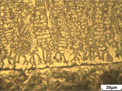
Figure 3.9 Photos of the metallographic structure of the cladding layer and bonding interface

Table 3.6 Hardness testing data
Flaw detection results:
The PT flaw detection results showed that there were no crack defects. As shown in Figure 3.10 below.

Figure 3.10 PT flaw detection defect-free area

Figure 3.10 PT flaw detection defect-free area
Thermal shock test (thermal shock test)
Thermal shock test (thermal shock):
For the quenching experiment in water at 600°C put the simulation piece into a heat treatment box and heat it to 600°C and keep it for 20 minutes. Take it out and put it in water to cool to room temperature. Then put it in a heat treatment box and heat it to 600°C and keep it for 20 minutes. Repeat this 10 times. After completion, PT flaw detection was performed and there were no crack defects.

Figure 3.11 Thermal shock test sample, no cracks in the PT flaw detection of the sample after the thermal shock test

Figure 3.11 Thermal shock test sample, no cracks in the PT flaw detection of the sample after the thermal shock test

Looper roller under repair

After repairing the looper roller